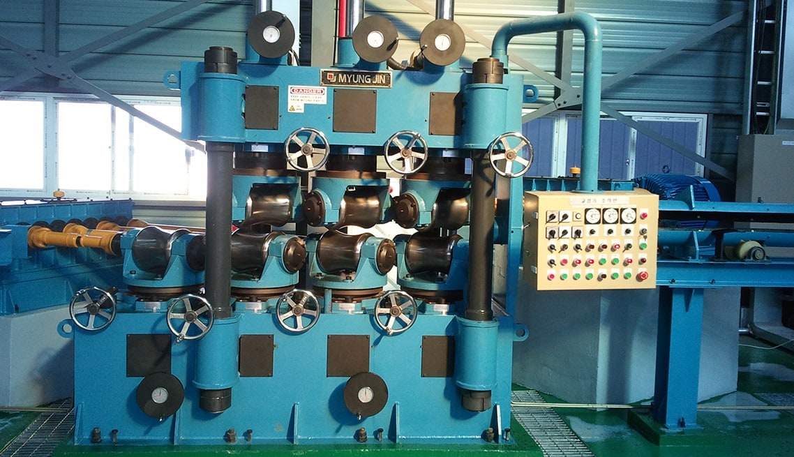
Straightening machine is a piece of industrial machinery used to level and flatten metal sheet or steel. It is also referred to as a straightening press. It can be either powered or unpowered.
As material and machine widths increase, the tendency of work rollers and end journals to deflect becomes greater. Excessive deflection can cause wavy edges and can lead to gear or journal failure.
Discs
Discs in a straightening machine can be used to correct defects on wheels. These defects can include wheel flanges that have changed their geometry. They can also be used to correct disc protrusion and extrusion. These issues can damage the surface of the wheel. This can be costly for the owner of a wheel repair shop.
The counter that secures the adjustable straightening discs on the sliding bush can be coupled to a piston / cylinder unit. This fulfills two functions, one is the positioning of only the adjusting disc with sliding bush for chamber dimension adjustment and the other last described pulling of the entire assembly on the bayonet ring 6 from the straightener shaft 1. It can be operated using a manual control valve. When the desired dimension is reached, the counter is switched off and the piston / cylinder unit is depressurized. This stops the process and allows the securing device to take over.
Hydraulic Cylinders
The demands for straightening precision in the conventional section-straightening machine necessitate a stiff and massive stand construction. This massiveness also results in a high load of the straightening shafts. This load is taken up by hydraulic cylinders. These cylinders have different sizes to allow greater or smaller forces to be supported depending on the lever ratios. The tool side cylinder is larger than the drive side cylinder.
The adjusting means for the bearing mounting pieces or units of the upper and lower straightening shaft parts are displaceable by pressure application via controllable hydraulic connections not shown. The two-sided journaling of the tool in this configuration enables a significant simplification of the replacement of tools or bushings with new ones.
This enables the insertion of tools for different sections without having to disconnect them from the straightening machine. This is possible because the movable base frame is opened by displacement of the manipulator through release of the prestressing sandwich connection.
Support Rings
During the straightening process, workpieces are subjected to high forces. These generate stress on the back-up rollers in a cassette (work and backup rollers). If these are not sufficiently robust, it can result in an expensive breakdown of the machine.
With their symmetrical construction, the cylindrical Support Rings Z and HZ are ideal for this purpose. They are available with measurement radii of 10 – 15mm, 11 – 13mm and 12.5 – 17mm.
A variety of trends in sheet metal processing make precision straightening technology particularly important. These include: narrower tolerance limits, a growing use of high-strength steels, and increasing demands in terms of surface flatness. In this context, igus lubrication-free plastic plain bearings are suitable as backup rollers in leveler and straightening machines. They are resistant to heavy loads and offer a combination of good rolling behavior and grease tightness. In addition, they are easy to install. This saves time and money during maintenance.
Rollers
A straightener requires a lot of power to operate. The amount of power required depends on several factors, including the maximum material thickness and width, and the work roller diameter and centre distance spacing. The bending resistance of the support journal and the friction between the work rollers and the metal are also major variables. It is important to carefully define all the variables for a particular application, because the power requirements can vary significantly.
In order to obtain a practical, useful end result, it is necessary to set the value bs 2 as precisely as possible. In practice, this means that a line with zero daylight must be detected at the beginning and the end of the straightened part. To do this, a ‘zero’ point is chosen for the upper and lower ‘fixed’ bank of work rollers. Ideally, this point is at the intersection of the directional triangles with the side length Dx. If this is not the case, then the resulting deviations will be too large to be useful.

